

- Home
- Products
- Rubber Products
- Rubbflex Couplings
Rubbflex Couplings
- Rubber Products
- Anti-vibration Rubber
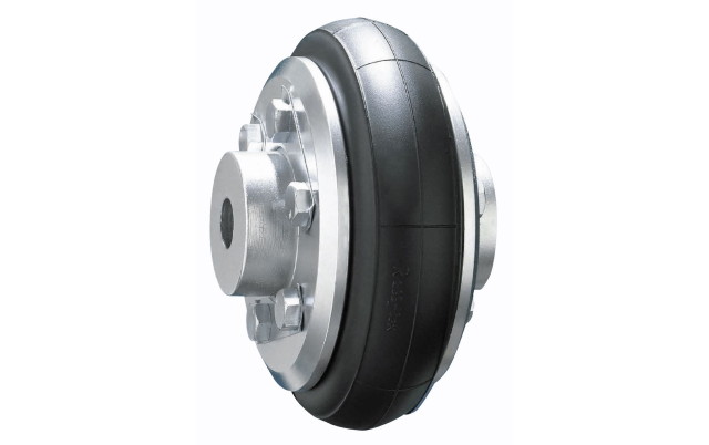
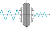
The tire-type coupling features flexibility and vibration absorption properties and has a strong reinforced fiber core with rubber that is resistant to bending fatigue.
Applications
• Rubber shaft couplings
Features
• Feature 1
The coupling tolerates a wide range of deflection angle, eccentricity, and gap error of highly flexible shaft. However, care must be taken when using the coupling under such specifications, as it may create a reactive force in proportion to the amount of deviation, resulting in damage to the device.
-
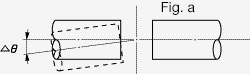
Deflection angle
The allowable deflection angle (Δθ) for each size is 3° or less for both axes.
-
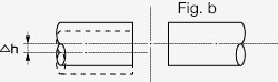
Eccentricity
The allowable eccentricity (Δh) for each size is 1% or less of the outer diameter of the coupling for both axes.
-
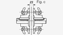
Gap error (end play)
The allowable gap between both flanges (Z2) for each size is 0 to -2% or less of the outer diameter of the coupling.
• Feature 2
The coupling has superior shock absorption and torsion damping. It is made of highly elastic rubber for extremely good absorption of shocks and vibration. This enables it to rotate very quietly and without vibration. The torsion angle of the coupling is proportional to the shaft’s running torque, facilitating design for cases in which the shaft vibration must be particularly taken into consideration.
• Feature 3
The simple structure enables easy installation and removal.
The rubber tire fastening hardware can be installed easily by tightening the bolt to move the pressure ring to the specified position (the stepped part of the flange boss in the RF-type or the groove in the flange boss in the RFH-type). Even if it is necessary to replace a coupling, a slit in the rubber tire at one location makes it possible to remove and replace the coupling without moving machinery.
• Feature 4
No lubrication is required, enabling easy maintenance and high cost-efficiency.
The coupling is almost completely unaffected by moisture and dust, meaning that it rarely requires maintenance. Because there is no metal friction area, it produces very little noise during operation, does not require lubrication, and generates no friction. The coupling reduces the cost for the coupling devices, making it more economical than other couplings.
Type
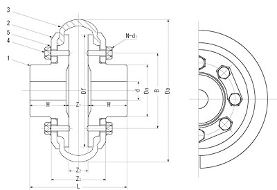
RF-type
| Part number |
Part name | Material | Surface treatment |
|---|---|---|---|
| 1 | Flange | FC200-equivalent | Lacquer coating (reddish brown) |
| 2 | Pressure ring | SS400 | Lacquer coating (reddish brown) |
| 3 | Rubber tire | Rubber, reinforced fiber |
− |
| 4 | Bolt | SWCH10R | Zinc plating |
| 5 | Common washer | SPCC | Zinc plating |
- Notes
- 1. Standard flange material is equivalent to FC200. (SS400 only for RF-60) Contact us if you require another material.
- 2. For RF-60 only, a spring washer is used instead of a common washer.
- 3. The bore size (d) will be finished using the “d min” dimensions unless otherwise specified. (φd tolerance: 0 to -1)
- 4. Appropriate ambient temperature is around +20°C. Use within an ambient temperature range of -10°C to +60°C.
| Outer dia. | Bore | Outer dia. of boss | Total width | Length of single flange |
Outer dia. of flange |
Flange separation |
Bolt pitch dia. |
Bolt size | Max. rpm |
Max. torque |
Mass moment of inertia |
Vibration moment |
Weight | ||||||
|---|---|---|---|---|---|---|---|---|---|---|---|---|---|---|---|---|---|---|---|
| Min. | Max. | Number of bolts | Nominal dia. × pitch | Length | |||||||||||||||
| Size no. |
Da | d min | d max | Dn | L | H | Df | Z1 | Z2 | Z3 | B | N | d1 × p | ℓ | n | T | I | GD2 | W |
| mm | mm | mm | mm | mm | mm | mm | mm | mm | mm | mm | mm | mm | r.p.m. | N·m | kg·m2 | N·m2 | kg | ||
| RF- 60 | 60 | 8 | 12 | 20 | 32 | 10.5 | 44 | 11 | 5 | 25 | 29 | 12 | M4×0.7 | 10 | 4,000 | 9.8 | 0.00008 | 0.0029 | 0.28 |
| RF-100 | 100 | 10 | 22 | 36 | 66 | 26 | 80 | 14 | 10 | 40 | 54 | 12 | M6×1 | 15 | 4,000 | 29 | 0.00088 | 0.0343 | 1.21 |
| RF-135 | 135 | 16 | 30 | 48 | 90 | 35 | 108 | 20 | 14 | 53 | 70 | 12 | M8×1.25 | 20 | 4,000 | 78 | 0.0038 | 0.151 | 2.87 |
| RF-180 | 180 | 23 | 35 | 64 | 120 | 46 | 144 | 28 | 20 | 70 | 95 | 12 | M10×1.5 | 25 | 3,000 | 147 | 0.0151 | 0.588 | 6.38 |
| RF-210 | 210 | 28 | 50 | 76 | 143 | 54 | 168 | 35 | 27 | 83 | 110 | 16 | M10×1.5 | 30 | 3,000 | 294 | 0.0319 | 1.25 | 9.40 |
| RF-265 | 265 | 33 | 60 | 95 | 178 | 67 | 210 | 44 | 32 | 105 | 140 | 16 | M12×1.75 | 40 | 2,000 | 736 | 0.101 | 3.96 | 19.0 |
| RF-310 | 310 | 36 | 70 | 112 | 208 | 75 | 248 | 58 | 36 | 121 | 165 | 16 | M12×1.75 | 45 | 2,000 | 1,230 | 0.224 | 8.77 | 31.0 |
| RF-400 | 400 | 40 | 85 | 145 | 270 | 100 | 320 | 70 | 44 | 153 | 210 | 16 | M16×2 | 55 | 1,600 | 2,700 | 0.791 | 31.0 | 70.0 |
| RF-450 | 450 | 55 | 100 | 165 | 300 | 110 | 360 | 80 | 50 | 171 | 240 | 16 | M20×2.5 | 60 | 1,250 | 4,900 | 1.39 | 54.6 | 101 |
| RF-550 | 550 | 90 | 130 | 200 | 365 | 130 | 440 | 105 | 53 | 196 | 280 | 16 | M24×3 | 75 | 1,000 | 9,810 | 3.78 | 148 | 170 |
| RF-700 | 700 | 100 | 160 | 255 | 460 | 165 | 560 | 130 | 70 | 256 | 364 | 16 | M30×3.5 | 100 | 800 | 19,600 | 12.6 | 492 | 358 |
Note 1: The figures in this table represent standard measurements at the time of temporary assembly.
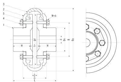
RFH-type
| Part number |
Part name | Material | Surface treatment |
|---|---|---|---|
| 1 | Flange | FC200-equivalent | Lacquer coating (reddish brown) |
| 2 | Pressure ring | SS400 | Lacquer coating (reddish brown) |
| 3 | Rubber tire | Rubber, reinforced fiber |
− |
| 4 | Bolt | SWCH10R | Zinc plating |
| 5 | Common washer | SPCC | Zinc plating |
- Notes
- 1. Standard flange material is equivalent to FC200. Contact us if you require another material.
- 2. The bore size (d) will be finished using the “d min” dimensions unless otherwise specified. (φd tolerance: 0 to -1)
- 3. Appropriate ambient temperature is around +20°C. Use within an ambient temperature range of -10°C to +60°C.
| Outer dia. | Bore | Outer dia. of boss | Total width | Length of single flange |
Outer dia. of flange |
Flange separation |
Bolt pitch dia. |
Bolt size | Max. rpm |
Max. torque |
Mass moment of inertia |
Vibration moment |
Weight | ||||||
|---|---|---|---|---|---|---|---|---|---|---|---|---|---|---|---|---|---|---|---|
| Min. | Max. | Number of bolts | Nominal dia. × pitch | Length | |||||||||||||||
| Size no. |
Da | d min | d max | Dn | L | H | Df | Z1 | Z2 | Z3 | B | N | d1 × p | ℓ | n | T | I | GD2 | W |
| mm | mm | mm | mm | mm | mm | mm | mm | mm | mm | mm | mm | mm | r.p.m. | N·m | kg·m2 | N·m2 | kg | ||
| RFH-100 | 100 | 10 | 22 | 38 | 63 | 25 | 80 | 13 | 5 | 38 | 54 | 12 | M6×1 | 15 | 5,000 | 49 | 0.00095 | 0.0373 | 1.22 |
| RFH-125 | 125 | 12.5 | 30 | 48 | 80 | 31.5 | 100 | 17 | 7 | 47 | 68 | 12 | M6×1 | 20 | 4,500 | 98 | 0.0028 | 0.110 | 2.12 |
| RFH-155 | 155 | 16 | 32 | 60 | 100 | 40 | 124 | 20 | 9 | 58 | 84 | 12 | M8×1.25 | 25 | 4,200 | 167 | 0.0080 | 0.314 | 4.56 |
| RFH-180 | 180 | 20 | 35 | 68 | 125 | 50 | 144 | 25 | 10 | 66 | 95 | 12 | M10×1.5 | 25 | 3,500 | 294 | 0.0169 | 0.657 | 6.88 |
| RFH-210 | 210 | 25 | 50 | 80 | 140 | 56 | 168 | 28 | 12 | 75 | 110 | 16 | M10×1.5 | 30 | 3,000 | 490 | 0.0355 | 1.39 | 9.79 |
| RFH-265 | 265 | 31.5 | 60 | 100 | 160 | 63 | 210 | 34 | 16 | 97 | 140 | 16 | M12×1.75 | 40 | 2,500 | 981 | 0.112 | 4.38 | 20.0 |
| RFH-310 | 310 | 40 | 70 | 118 | 200 | 80 | 248 | 40 | 18 | 113 | 165 | 16 | M12×1.75 | 45 | 2,000 | 1,370 | 0.248 | 9.73 | 35.0 |
| RFH-400 | 400 | 50 | 85 | 152 | 250 | 100 | 320 | 50 | 23 | 143 | 210 | 16 | M16×2 | 55 | 1,600 | 3,140 | 0.863 | 33.8 | 75.0 |
| RFH-450 | 450 | 63 | 100 | 172 | 315 | 125 | 360 | 65 | 25 | 161 | 240 | 16 | M20×2.5 | 60 | 1,400 | 4,900 | 1.56 | 61.1 | 115 |
| RFH-550 | 550 | 80 | 130 | 210 | 355 | 140 | 440 | 75 | 30 | 191 | 280 | 16 | M24×3 | 75 | 1,100 | 9,810 | 4.22 | 166 | 190 |
| RFH-700 | 700 | 100 | 160 | 266 | 450 | 180 | 560 | 90 | 40 | 246 | 364 | 16 | M30×3.5 | 100 | 900 | 19,600 | 14.2 | 557 | 400 |
Note 1: The figures in this table represent standard measurements at the time of temporary assembly.
Inquiries
We welcome questions and comments on any of our products and services.
Please contact the receptionist below for any questions.
* Exportable Products/Foreign countries have been limited. Please take note that we may not accept all your inquiries, in some case.
MAIL: